We’re getting a lot of questions about RFI and EMI attenuation, static pressure, and airflow in HVAC air ducts that penetrate secure buildings and SCIF enclosures.
Enclosures, whether they’re built for human use or sensitive electronic equipment, require openings for conditioned air to enter the space for temperature control, ventilation, or both. As we pointed out in a previous post:
But you need ventilation panels. They must do things like keep electronics cool or military shelters livable with circulating fresh air and, in some instances, be placed in-line with heaters or air conditioning units. Considering the varying degrees of shielding required, the various levels mandated for civilian and military use, and the numerous possible environments a hardened enclosure must be built for, there are many variations of EMI shielded ventilation panels.
Airflow is a necessary design factor to be considered when designing occupied enclosures like SCIFs and secure buildings, as well as equipment enclosures that require airflow for ventilation and/or temperature control.
Specialized ventilation panels are designed to protect against EMI and RFI signals, incoming and outgoing, of proximal electronic equipment in order to protect against crosstalk and un-intended external monitoring of interception..
There are some unique challenges for EMI and RFI engineers, designers, and system integrators surrounding airflow into and out of secure enclosures, however. And that’s what we’re going to cover in this post.
Here’s what you’ll learn:
- How do Honeycomb waveguide panels work, and why should you use them?
- How is EMI/RFI shielding effectiveness accomplished and measured in HVAC systems?
- What are the primary HVAC and airflow design considerations?
- What does vent panel installation look like in practice?
- Tying it all together and where to go for more information and resources
So let’s get started with the fundamentals.
But First, a Quick Video.
How do Honeycomb waveguide panels work seamlessly to provide optimum airflow and effective EMI/RFI shielding in HVAC systems?
Honeycomb waveguide vent panels from MAJR Products are designed to provide maximum simultaneous EMI signal attenuation and airflow. The honeycomb cell apertures are designed to be sized generally at 0.060 in. diameter for higher frequency applications above 18 GHz. For frequencies below 18 GHz a standard honeycomb cell aperture of 0.125 in. can be used. Other larger size cell apertures such as 0.188 in. and 0.250 in. can be used when static pressure drop needs to be less than the 0.125 in. cell aperture. There is a trade off with a larger cell aperture such that the larger the cell the less attenuation at frequencies approximately above 1 GHz due to the wavelength dimension. The key is to allow maximum airflow (minimum static pressure drop) but meet the EMC shielding requirements.
In a nutshell, the honeycomb cell geometry allows for optimum “open space” surface area for airflow while maintaining theEMI/ RFI shielding requirement of the enclosure.
How is EMI/RFI shielding effectiveness accomplished and measured in HVAC ventilation systems?
The gold standard framework for defining the attenuation effectiveness of electromagnetic shielding in enclosures is MIL-STD-285 and/or IEEE-299.
So let’s examine how EMI and RFI Shielding effectiveness is measured. We went to the compliance testing experts at Keystone Compliance for some initial guidance:
One of the main components of shielding effectiveness is attenuation. Attenuation is a ratio, expressed in decibels (dB). The ratio is of the received powers on opposite sides of a shield when the shield is illuminated by electromagnetic radiation. Per MIL-STD-285, this is the figure of merit to designate the shielding effectiveness of electromagnetic enclosures
EMI/RFI attenuation is measured in decibels (dB), and it’s usually graphically represented on a logarithmic 2D scale. So, for example, 10 dB of EMI shielding will attenuate the energy of the signal wave by a factor of 10, 20 dB will reduce it by a factor of 100, 30 dB by 1000, etc.
It is also important to note that the shielding effectiveness of the honeycomb vent panel will differ depending on the wavelength of the impending signal to be blocked.
EMI/RFI shielding effectiveness measures how effectively the shielding component, in this case, honeycomb vent panels, protects against EMI/RFI. This metric is essentially measured as the difference in strength or intensity of an electromagnetic signal before the shielding component and then after it is installed. As mentioned earlier, the efficacy of the vent panel also depends on the size of the cell aperture and frequency (wavelength) of the signal (EMI/RFI) required to be attenuated.
The Shielding Effectiveness vs Frequency table below demonstrates the shielding levels of MAJR Products vent panels for different plating and core materials at various frequencies.
Shielding Effectiveness vs Frequency
Shielding Effectiveness dB
| Field | Aluminum - Chromate Finish Material Code - 32 Frequency |
|||||
| 1 MHz |
100 MHz |
500 MHz |
1 GHz |
10 GHz |
18 GHz |
|
| E | 60 | 50 | 50 | — | — | — |
| PW | — | — | — | 45 | 40 | 30 |
| Field | Aluminum - Tin Plate Material Code - 42 Frequency |
||||||
| 1 MHz |
100 MHz |
500 MHz |
1 GHz |
10 GHz |
18 GHz |
||
| E | 100 | 90 | 85 | — | — | — | |
| PW | — | — | — | 80 | 70 | 60 | |
| Field | Steel - Tin Plate Material Code - 44 Frequency |
|||||||
| 10 kHz |
100 kHz |
1 MHz |
100 MHz |
500 MHz |
1 GHz |
10 GHz |
18 GHz |
|
| H | 45 | 60 | — | — | — | — | — | — |
| E | — | — | 110 | 110 | 110 | — | — | — |
| PW | — | — | — | — | — | 110 | 80 | 70 |
The data in the table shows shielding characteristics for standard MAJR shielded vents. Note that the data indicated is based on a unit whose opening was 12.00” x 12.00” using a 0.5” x .125” cell size honeycomb and tested under laboratory conditions per MIL-STD 285. Tin Plated Steel data reflects a steel honeycomb and steel frame construction. Not all mounting frame options are available in steel.
Here are some basic design considerations to keep in mind:
- Required shielding levels (ex: 60 dB shielding at 10 GHz)
- Electrical and Magnetic (E & H) field strength requirements
- Overall, and duct or aperture, dimensional measurements
- Mounting Method (ex: Mount within ducts, wall surface mounting, captive fasteners, etc.)
- Airflow and static pressure requirements
Remember, the primary purpose of shielded ventilation panels is to block EMI/RFI/EMP, protect sensitive electronics, and ensure privacy in secure buildings and enclosures, like SCIFs.
What are the primary HVAC and airflow design considerations?
This is the part where mechanical and electrical engineering considerations cross paths. Engineers and designers need to design for EMI/RFI signal attenuation while ensuring optimized airflow and static pressure drops.
The basic HVAC design considerations are twofold:
- What volume of airflow, in cubic feet per minute, or CFM, is required for air conditioning or ventilating the space?
- How much static pressure will be lost through the introduction of the vent panels?
This is where the optimum shielding and airflow provided by MAJR Products’ Honeycomb waveguide vent panels come into play.
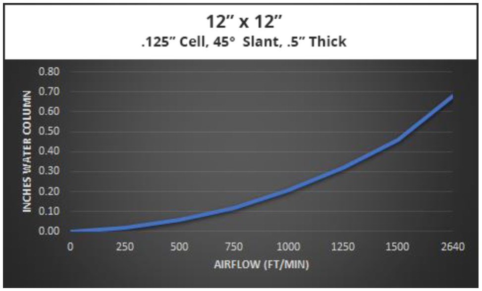
The honeycomb cell design, with an optimal 4:1 opening to cell depth ratio, provides a waveguide below cut-off effect required to attenuate EMI/RFI interference. The thin metal cell walls maximize airflow area also allows for maximum CFM at low static pressures; therefore airflow requirements for HVAC and ventilation are maintained along with the EMI/RFI shielding requirements of the enclosure. The Air Flow Resistance graph below demonstrates airflow and static pressure for a Honeycomb waveguide vent panel.
If you need extra environmental protection for ventilation, add 45°, 30°, or 15° slanted honeycomb. Angled honeycomb panel configurations can serve as ventilation splash guards and provide more surface area for filtration and attenuation. Just be aware of static pressure considerations, as illustrated in the Design Data: Airflow graph below.
Design Data: Airflow
So, what does vent panel installation look like in practice, and are there design resources?
Installing Honeycomb waveguide ventilation panels is fairly straightforward in ductwork and in wall or ceiling apertures. Waveguide vents are supplied with installed EMI shielded gaskets and mounting holes ready for installation.
We have a variety of panels and installation styles to meet all needs: Surface Mounted, Slide-In Mounted, and Recessed Mounted.
We also have additional installation guides and technical specs for engineers and designers.
Where can you go for more information and resources?
MAJR Products is an internationally recognized leader in designing and manufacturing the highest quality shielded ventilation panels.
We’re here to ensure you have the right solutions for your military or civilian use applications, standards, and project requirements. Our team will help you confidently spec and source shielded vent panels with the attenuation characteristics, sizes, material combinations, and configurations you need.
Get an HVAC Waveguide Estimate
You can contact us online or call us anytime at (877) 625-6033.
Subscribe
Data Sheet Download
Data Sheet Downloads -
Click Here For All Our Data Sheets